How to Assembly an Electromagnetic Clutch

How to Assembly an Electromagnetic Clutch

How to Assembly an Electromagnetic Clutch

Complete Installation Guide

Proper mounting of an electromagnetic clutch is crucial to ensure efficient operation of industrial and agricultural machinery. In this comprehensive guide, we explain step by step how to perform a professional installation, the available mounting types, and the most important technical considerations.

What is an Electromagnetic Clutch?

An electromagnetic clutch is a device that uses the electromagnet principle to couple and decouple two rotating shafts. It works through a stationary coil that generates a magnetic field, attracting a mobile armature when direct current is applied, thus creating the mechanical connection between the two parts.

Main components:

  • Electromagnetic coil: Generates the magnetic field
  • Coil holder or inductor: Concentrates the magnetic force lines
  • Armature or induced element: Element that is attracted when energizing the coil
  • Friction material: Provides adherence and durability
  • Rotor: Rotating contact surface

Types of Electromagnetic Clutches and Their Mountings

1. Clutches with Slip Rings
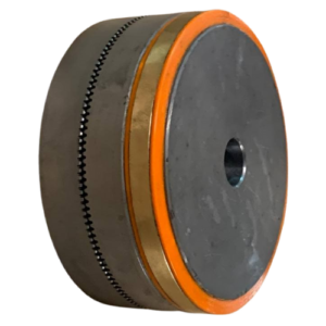
ECD Electromagnetic Tooth Clutch

Characteristics:

  • Coil holder connected to a hub with slip rings
  • Electrical supply through fixed brushes
  • Simpler and more economical construction
  • Requires brush maintenance

Mounting:

  • Fix the hub with slip rings to the driving shaft
  • Install the brush holder in a stationary position
  • Verify correct brush pressure
  • Connect electrical supply through the brush system

2. Clutches with Stationary Coil and Rotor
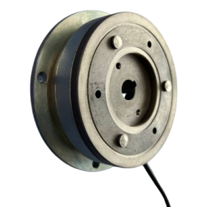
Embrague electromagnético OLK

Characteristics:

  • Fixed coil mounted on the machine
  • Rotating rotor as friction surface
  • Longer service life and less maintenance
  • Better operating precision

Mounting:

  • Fix the coil holder to a static part of the machine
  • Align the rotor perfectly with the driving shaft
  • Verify concentricity and perpendicularity

Step-by-Step Mounting Process

Preliminary Preparation

  1. Technical specification verification
    • Required torque vs nominal clutch torque
    • Maximum rotation speed
    • Supply voltage (generally 24V DC)
    • Mounting dimensions
  2. Required tools
    • Allen keys and fixed wrenches according to specifications
    • Calibrated torque wrench
    • Multimeter for electrical verifications
    • Calliper, micrometre or feeler gauges for precision measurements

Mechanical Mounting

Step 1: Coil Holder Installation

  • Position the coil holder in the final location
  • Ensure fixation to a completely static part
  • Verify that there is no movement or vibration
  • Apply the specified tightening torque for the screw size

Step 2: Rotor Alignment

  • Mount the rotor to the driving shaft with the corresponding key
  • Verify concentricity using a dial indicator
  • Ensure there is no metal-to-metal contact at rest

Step 3: Armature Installation

  • Place the armature on the driven shaft
  • Adjust the position to obtain the correct air gap
  • Check that the air gap is uniform (typically 0.3 – 0.5 mm)
  • Fix using the clamping system (key, set screw, etc.)
  • Verify freedom of axial movement

Electrical Connection

Basic Supply Circuit

Typical supply requires:

  • Transformer: From 220V AC to required voltage (normally 24 VDC)
  • Rectifier: Conversion to direct current
  • Protections: Fuses and overvoltage protection elements

Recommended Connections

  1. Direct current side
    • Connect positive to one coil terminal
    • Negative to the other terminal
    • Install a protection diode in parallel (optional)
  2. Protection elements
    • Varistor or Zener diode to protect contacts
    • Capacitor in parallel to smooth disconnection

Important Technical Considerations

Rotation Speed

  • Maximum RPM: Never exceed tabulated limits
  • Dynamic torque: Decreases with slip speed
  • Thermal dissipation: Improves at high speeds due to fan effect

Break-in Process

New clutches require a break-in period:

  • First operations may show reduced torque (up to 50%)
  • Several hundred actuations are needed for complete break-in
  • Higher relative speed means shorter break-in time
  • In low-speed applications, consider doubling the selection torque

Preventive Maintenance

  • Regular air gap inspection: Must remain uniform
  • Friction material condition: Check wear and contamination
  • Electrical connections: Check tightness and oxidation
  • Alignment: Verify no misalignments due to use

Common Problem Solutions

Problem: Insufficient torque

Possible causes:

  • Excessive air gap
  • Low supply voltage
  • Contaminated or worn friction material
  • Incomplete break-in process

Solutions:

  • Adjust air gap according to specifications
  • Verify supply voltage
  • Clean or replace friction material
  • Allow more break-in time

Problem: Excessive noise during engagement

Possible causes:

  • Mechanical misalignment
  • Irregular air gap
  • Inadequate friction material
  • Too high engagement speed

Solutions:

  • Verify and correct alignment
  • Adjust air gap uniformly
  • Consider a low coefficient of friction material
  • Implement engagement speed control

Proper mounting of an electromagnetic clutch requires meticulous attention to mechanical and electrical details. Following these guidelines ensures:

    • Reliable and durable operation
    • Maximum utilisation of equipment characteristics
    • Extended maintenance intervals
    • Precise and repeatable operation

For specific applications or technical questions, it is advisable to consult with specialists in the field, who can provide personalised advice according to the particular conditions of each installation.

Need help with your industrial automation project? At EIDE we have the experience and products necessary to implement electromagnetic clutch solutions adapted to your specific needs.

2025 All Rights Reserved © EIDE | Powered by TIC BCN